|
|
 | Saturday, July 4, 2026 |
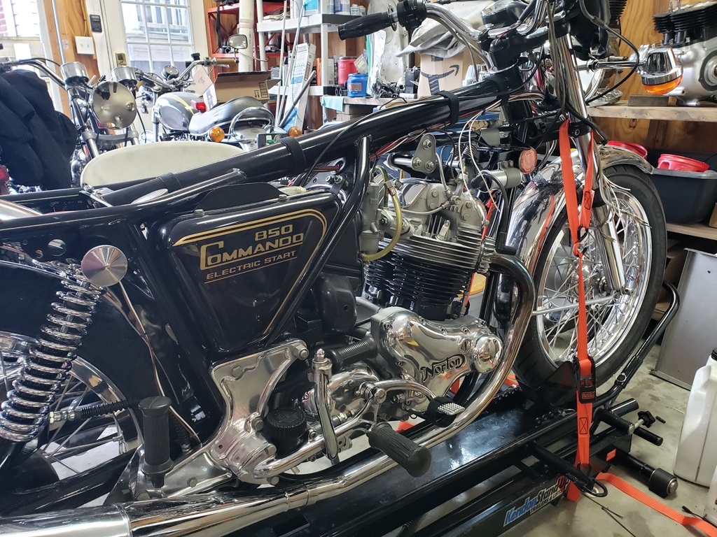
I've already detailed the wiring of a 1972 and a 1974 Commando from scratch. This will be a little different. I've got a rebuilt but unwired MK3 in the shop to be wired for a customer. This bike will be wired similar to the others with the goal of reducing as many connectors as possible and using heavier gage wire where needed.
All these things will be eliminated:
- Dual Zener diodes
- Bridge Rectifier
- Points
- Condensers
- Ballast Resistor
- Assimulator
These things will be added:
- Tri-Spark Tri-0006 Electronic Ignition.
- Tri-Spark VR-0030 MOSFET Regulator
- Oil Pressure Switch
I'm also considering how to reduce the number of battery connections. This bike has a huge AGM battery so it's not a big deal to have multiple wires on the terminals, but when a small Lithium battery is used it is hard to keep them in place with lots of connections.
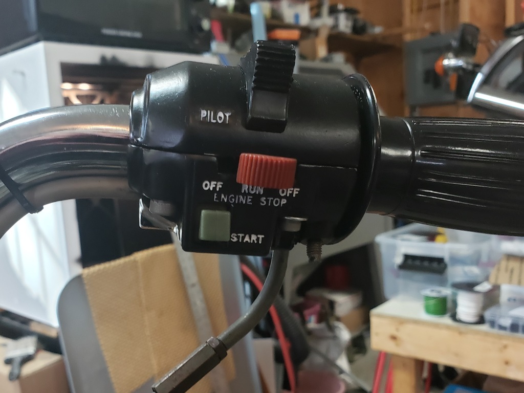
The other issue is the handlebar central console - these are a PITA to work on and I want to see if I can make that better.
I've got one bike to finish and get off the table so this one can go on - then I can start working on it in earnest. Right now, I'm just studying a little on it. At my age, no working on bikes on the floor!
April 6, 2024 Found some really nice replacement LED lights for the console. Have a new sticker for the console on order Once that's here, I'll be able to assemble it.
April 9, 2024 All projects ahead of this one are stuck waiting for parts to arrive! So, at least for today and tomorrow, this one is getting attention. First up is mounting the Tri-Spark MOSFET voltage regulator. I have favorite places to do that with the models that came with the "hamcan" air filter. The MK1A, MK2A and MK3 have none of those places available. For MK1A and MK2A, I use the rear fender - a little fiddly but a solid solution. The MK3 can't use that solution because then the toolbox would not fit.
This one is going on the bracket between the frame and rear fender.Others have done that but I do it differently. I braze the 5/16" bolt that connects the bottom of the bracket to the fender to the bracket since it's not accessible once the regulator is installed. Then two holes are drilled to mount the regulator. Of course, I ran out of oxygen while brazing and I put the new holes too high on the bracket so it couldn't be installed :-(
That's all fixed now and I'll powder coat the bracket tomorrow.
April 10, 2024 Went on a hunt for the stator wires today - couldn't see them anywhere. Finally removed the starter and fished them out. Started running wires. Every time I document a wiring job people later complain that I didn't give enough detail. I'm going to try again to correct that.
Notes:
- I cut wires longer than needed. When running wires, it often turns out that between bundling, fitting around things, and so on that the wires seem to get shorter. There's nothing worse than having to splice on more wire or run a new wire. If you are frugal, you probably can cut wires shorter than I specify, but I certainly wouldn't!
- I buy all my supplies from British Wiring I have no relationship with them, I am simply a customer of theirs. Where I've document a product of theirs, I included their part number.
- Where I say "buy" I mean how many/much to buy.
- If wiring a pre-MK3 Norton, I recommend reading through this and following this: Norton 1974 Wiring Differences in the master switch location, flasher location, and headlight verses center console mean that they are similar but different.
The first task in each wiring job is the five headlight to taillight wires. These are all 79" long (2m). Edit: 4/28/2024 - I went a bit overboard on the extra length - cut each of the wires below to at least 73".
- 14ga Red, Ground, buy 3m (C128)
- 18ga Brown, Brake, buy 4m (C114)
- 18ga Brown/Green, Lighting, buy 4m (C114)
- 18ga Green/White, Right Side Turn Signals, buy 3m (C114)
- 18ga Green/Red, Left Side Turn Signals, buy 3m (C114)
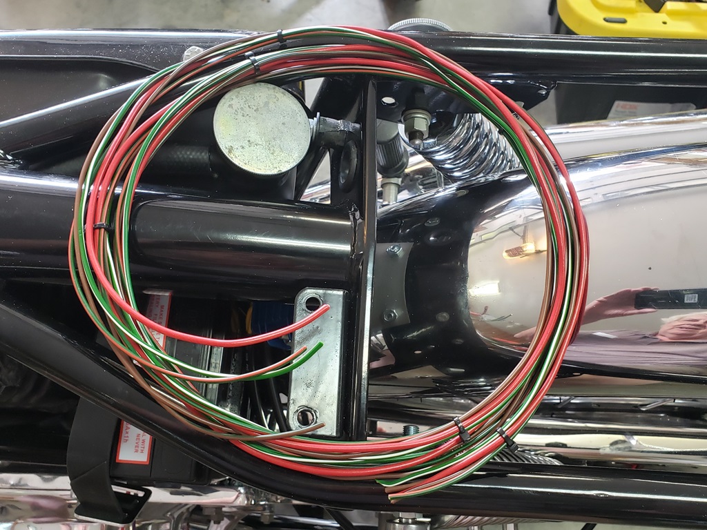
It's best to bundle these together and route them - figuring the routing of these out will make the rest of the wires clearer.
April 11, 2024 Removed the started and found the stator wires. Need to understand why the 3rd started screw that goes through the cases into the starter was a short screw and screwed into the inner chaincase like the others.
April 12, 2024 Got the console label today. The console looks really good. I would have finished it, but I would like to find a way to not solder the wires in case a LED goes out. The lights drop in from the front and have a nut on the back. If soldered, to replace one will require cutting the wires is soldered. They are LEDs so very unlikely to go out. I found a set of connectors that supposedly would work - they are on their way back to Amazon - didn't work as advertised! I have another set coming tomorrow. If they work I'll use them, otherwise, I'll leave a little extra length and solder the wires.
Of course the LEDs are wired for negative ground, but that's no issue as I'll go from them using the correct colors to the harness. Since the turn indicator is an LED, I'll also add the two diodes to make it work.
April 14, 2024 The new connectors had a different write-up but were identical and cannot be used. I studied on it and have a plan for wiring the console that will still be relatively easy to change one of the lights if it is ever needed. More later. I also, messed with routing of the 6ga starter wires. That's all figured out now as well as the routing of the regulator yellow wires. Also, I confirmed that there will be no red wire to the battery and the Brown/Blue will go to the un-switched side of the starter solenoid. The nuts on the starter solenoid have seen better days so I ordered replacements. I still have to verify that the solenoid is good!
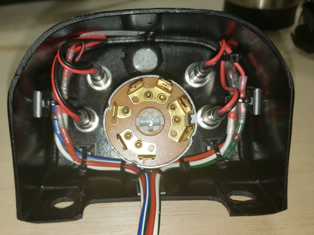
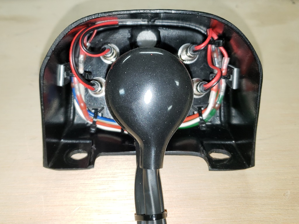
The warning lights come with ring nuts and an o-ring. When I first put them in the console, the o-rings slowly buckled the sticker. So, I took them back out, smoothed the sticker, took the o-rings off and put each light in, then its o-ring, then its nut. This keeps the sticker nice and acts to lock the nut in place.
April 18, 2024 Is there anything worse than a brain fart? Started wiring the console today and wanted to knock out the most fiddly part first - the diodes to let the LED turn signal indicator to work I've understood diodes since college in 1966. Why in the hell did I look at the correct symbol on my special schematic and think about it backwards. I put together with a photo at each step for a tutorial and it doesn't work because the diodes or the LED is backwards (two ways they can be wired). Grrrrrrrrr!
April 19, 2024 Actually there is something worse - brain farting on you brain fart! It turns out that the diodes were wired right, the LED was backwards! I got confused because I was thinking that the wire colors are backwards from positive ground and that I would have to splice or mark them all - silly, red is still positive and black will translate to whatever color it needs to be for other circuits. Only when an indicator doesn't go directly to ground will I have to do something. In any case, the correct wire colors will connect to the main harness.
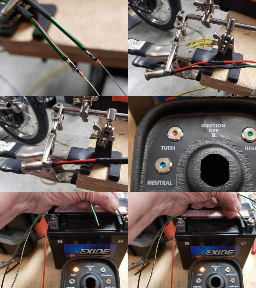
Below is a montage of the steps.I had this much more details but lost half the pictures. Still it shows how to do it.
- The end of each diode with the line goes to the control wire which connects the actual indicator wire. Green/White is right side, Green/Red is left side.Then both get heat shrink to cover the connection and diode.
- The other ends of the diodes get connected together and connected to the negative side of the LED (black wire). Then covered with heat shrink.
- Since I had the diode backwards I had to splice the red wire
- The Red wire goes to positive ground as usual for a Norton.
- In the last two pictures you can see that whether the Green/White or Green/Red is connect to power (negative), the LED lights. When the Green/Red and Green/white wires are connect to the main Green/Red and Green/White, the indicator will flash with the turn signals.
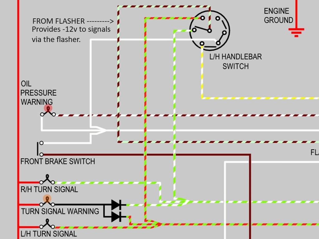
Below the pictures is a snippet of the wiring diagram showing the diodes, LED and all wire colors involved.
One side of the flasher has a white wire (-12 volts). The other side has the LightGreen/Brown wire that goes to the handlebar control. If that console is on the left handlebar, then up connects the LightGreen/Brown to the GreenWhite and the right-side turn signals flash. If down then the LightGreen/Brown is connected to the Green/Red and the left turn signals flash. Since the indicator wires are connected to the two sides via diodes, the indicator flashes with the turn signals.
April 22, 2024 I've been trying to finish up a bike but along the way still gathering things for this project. Like a big dummy, I ordered some wire I was out of and no bullets. I was sure I had them. As I was putting the order away, I notice no bullets! So, a second order (with more ridiculous shipping) and I got a bunch more. Of course, when I went to put them in the bin, I stumbled across the unopened package of 100 that I did not put in their proper place - I swear I need a keeper!
Next thing, I wanted Zip Tie mounts for the inside of the console and had none of them. Last time I used them I thought they were 3/4" and that seemed too big for the inside of the console so I searched long and hard and found 1/2" square mounts - the cute little buggers arrived today. Turns out that what I was used to were 1" square. Assuming these hold, they will be good. They have very sticky 3M foam double stick tape on them so they probably will. The are not strictly required but I like wiring to be compact and to stay into place. This is ready a nasty environment if riding in the rain.
April 23, 2024
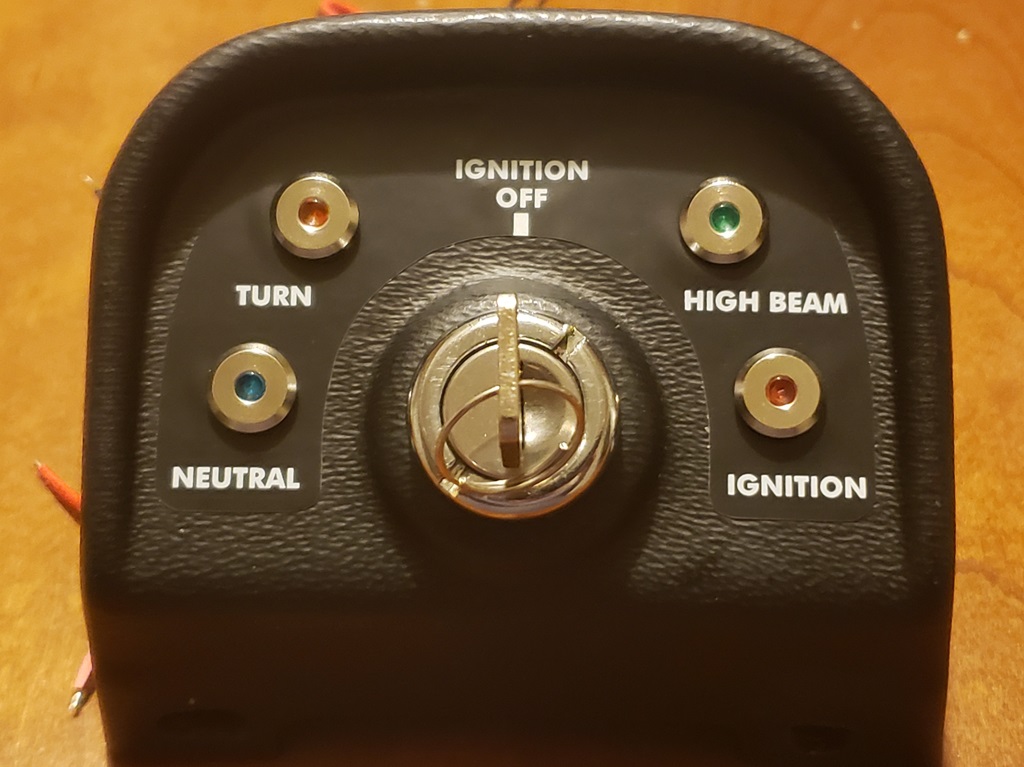
Back on the console and it's coming along nicely. But, I almost made a mistake. All Lucas equipped bikes I've ever worked on that had a high-beam indicator used green for that. Not the MK3! It uses blue for high-beam and green for neutral. Fortunately, I caught that before having to order more lights! The LEDs come with very fine black and red wires so I'm splicing them to the correct colors and with 9-strand wires where the right colors were available and 14-strand (18ga) where not. They will use standard bullets in any case. If an indicator ever goes out, it can be removed and replaced without much trouble. Initially I was going to do it with plugs but I never could find plugs compatible with the very fine ware and 9- or 14-strand wire. The splices I'm using are waterproof and so are the LEDs. The little tie downs are working very well. This will actually be very neat when done.
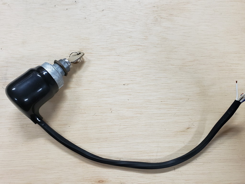
April 24, 2024 It probably seems like I'm making the console my life's work! The indicators are all wired and tested and I'm happy with the results. I still have to wire the master switch but I'm going to bundle those wires separate from the indicators - they will run together to the headlight shell, but in separate covers.
April 25, 2024 Started to do the master switch wiring and then realized that the MK3 switch cover is different than the pre-MK3. I don't have an MK3 switch overs :-(. So, I"m placing an AN order tonight.
I remembered that I didn't talk about wire lengths for the wires to the indicators. There are 8 wires and where I could get the right colors in 9-strand I used that. The rest are 14-strand but they are not a lot thicker. Since I don/t have long lengths of 9-strand, I was conservative with the lengths. 9-strand and 14-strand take different bullets that are identical on the outside so they work fine in the connectors. Wire finer than 9-strand doesn't work well in bullets which is why I had to splice Red to Red in some cases.
I cut each indicator's wire to 2-3" staggering each. Then used splices that solder and waterproof with a heat gun. The final overall length of the wires is about 16". Edit May 1, 2024 Make these 18" - 16" is OK, but 18: will make the wiring in the headlight shell easier. Edit May 22, 2024 I'm in the process of termination connections and it is working out OK, but I will extend a couple of wires - make these 24"! Life will be much easier! There is not as much slack as I like at this point but they will be plenty long enough. This bike has an oil pressure switch rather than an assimulator so here are the wires:
| LED Color |
Function |
LED Red Wire |
LED Black Wire |
| Red |
Oil Pressure Warning |
Spliced to White/Brown which goes to the oil pressure switch |
Black spiced to White which is negative. |
| Green |
Neutral Indicator |
Red spliced to Green which goes rt the neutral switch |
Black spiced to White which is negative. |
| Blue |
High Beam Indicator |
Red spliced to Red which goes to ground |
Black spiced to Blue/White which goes to the high beam Blue/White |
| Amber |
Turn Signal Indicator |
Red spliced to Green which goes to the neutral switch |
Black spiced to White which is negative. |
In the picture above I show all indicator wires bundles and tied down. This leaves little room for the switch with cover so they probably will be split into left and right bundles - haven't decided yet.
As I do with all bikes, the master switch will be wired this way:
Pin 1: 14ga Brown/Blue which ends up at battery negative via the fuse.
Pin 2: Three 18ga White wires. One to the left-hand handlebar console, one to the right-hand console, and the other to the other white wires.
Pin 3: 18ga Brown/Green wire that connects to the other Brown/Green wires and lights the taillight, pilot light and instruments lights.
Pin 4: 18ga Blue/Yellow wire that enables the headlight
These wires are all cut to 15". Two white wires will be terminated by on female standard spade connector. The other white wire and the two other wires each get terminated in a standard spade connector. The other ends will get the appropriate sized bullet once final wiring and cutting to length is done.
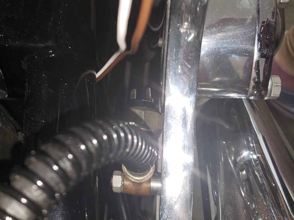
April 26, 2024 Now were getting somewhere! I was planned to run the rear brake wires down the front of the two angled frame tube as the back. It took a while to take the blinders off and switch to the rear tube. The first picture show how hard the switch is to get to and how the wires will get there
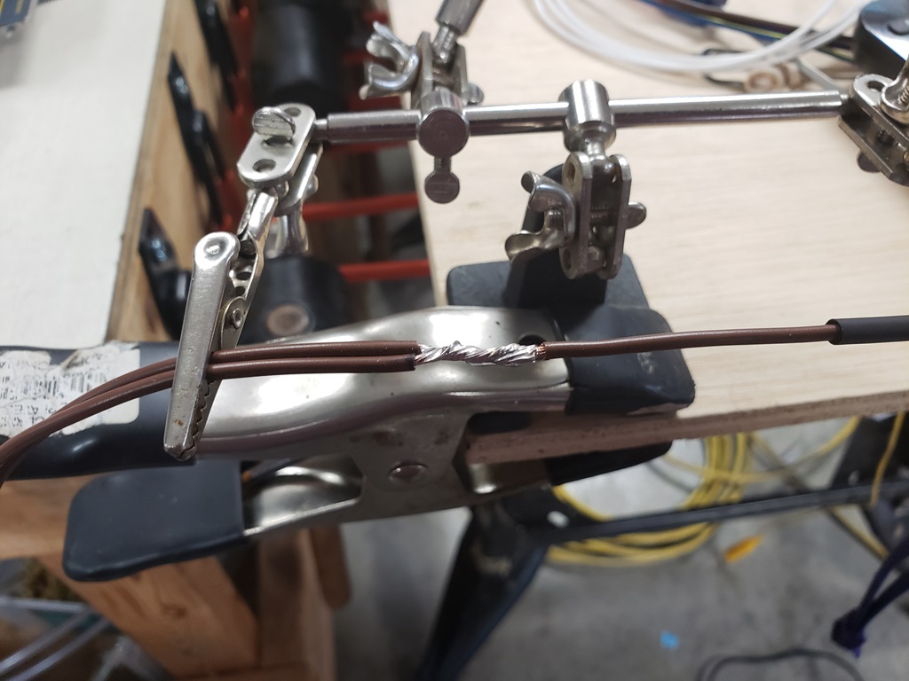
The second Picture was supposed to be three pictures but the other two didn't come out. When I splice wires, the first steps is a solid connection between then, then solder, then a piece of heat shrink just long enough to cover the bare wire and finally another piece of heat shrink that extends about 1/4" past each end of the first piece.
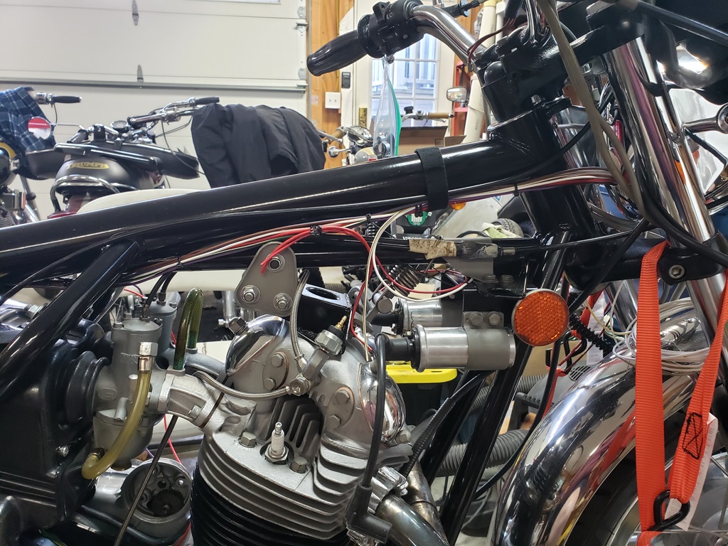
The third picture shows all the main wired run. There are three more splices to do. Where you see two zip ties together the wires will break out of the harness. Under the tank, there one 14ga Red wire that will connect to the head steady Allen bolt closest to the timing side. On a MK3 there is a heavy ground wire to the engine - this 14ga Red wire is the ground of the rest of the bike. The 18ga Red wire exiting the harness by that 14ga Red wire goes to the + of the coil on the drive side. Normally, the oil pressure switch connects to the rocker feed from the engine, but the owner modified it to be connected to the top of the rocker feed so the White/Brown wire goes there. The White/Yellow wire from the kill switch exits the harness with the White/Brown and will connect to the Black/Yellow from the Tri-Spark. The Black/White (not yet run) will connect to the - of the timing side coil.
Once the splices are done, I can add sleeves/heat shrink where needed and then wrap the harness. One thing I'm not looking forward to is checking/cleaning the handlebar consoles and figuring out all the wrong colors they have - I can't figure out why the didn't use standard colors!
April 28, 2024 All wires have now been run. The thing that tales the longest time is putting the harness or and taking it off many times. This is needed to ensure that the breakouts happen at good places, that the wires that leave the main trunk are long enough, and that everything routes. All the breakout locations are finalized in the front half of the bike and all the wires that connect to things are at least a little long. Each will get a sleeve or heat shrink even though it's overkill. As you can see, there are very few wires under the tank and once terminated, they will be even harder to see.
April 29, 2024 The AN parts arrived today and I was able to finish the console. I'm really happy whit the way it turned out.
April 30, 2024
All along the way when wiring I'm make sure all wires are run and all are the right lengths so when I wrap and then terminate there are no problems. Here's one step of that. But wait! Why are my fingers wet when putting on the console? Hydraulic leak - that's why. That was easty to fix.
With all (wait for it) the wires routed to the headlight shell, I could mentally go through the connections. This ai't horseshoes - close is not good enough! First I noticed no wires for the instrument lights - OK dug those out of the box of stuff that came with the bike, checked them and cleaned them. Then I got to the White/Red wire from the handlebar console starter button - where the devil is the White/Red in the harness - I forgot it! Sure Glad I check myself! The other almost issue is that the wires from the console LEDs could have been a little longer - I"m sure they are OK, just would have made connecting things a little easier. Also, during this process I realized that splitting those wires into two bunches ended up being a really good idea.
Don't worry, the handlebar console will come off, be checked and the cables will look nearly new before they go back on.
May 1, 2024 I have two sold bikes to get out the door and I finally have everything to get that done so I'll be off this for a while.
May 7, 2024 A little more progress today. Working on the starter solenoid and wiring and routing to it. That's all figured out and the main harness breakouts and defined. The solenoid was bothering me because I was getting four ohms across the cables when engaged. That turned out to be corrosion. That's all cleaned now, and the resistance is zero ohms now as it should be.
May 9, 2024 Spent a good bit of time figuring out how I'll do the starter solenoid and where the final harness breakouts need to be. Then did all final splicing. For those wanting to know, I'll lay the harness out, annotate,and provide the lengths. Of course, once wrapped, 'll start terminating and some wires will be shortened.
I'm going to use a couple of connectors in the battery area that I hoped not to use, but getting the solenoid and battery in a out is difficult enough and would be really hard is all were terminated at the solenoid. Some still will be but with enough length to disconnect them one the solenoid is out. I also went to great care to ensure the solenoid could lift straight up after removing the two mounting screws.
May 10, 2024 Still screwing around with the solenoid and wiring but getting closer to happy. The short heavy wire to the battery "-" can be removed without taking the solenoid off. The ground wire and starter wires are getting a connector to the main harness. The long heavy wire between the solenoid and starter has enough slack that the solenoid and be lifted up and then the wire removed.
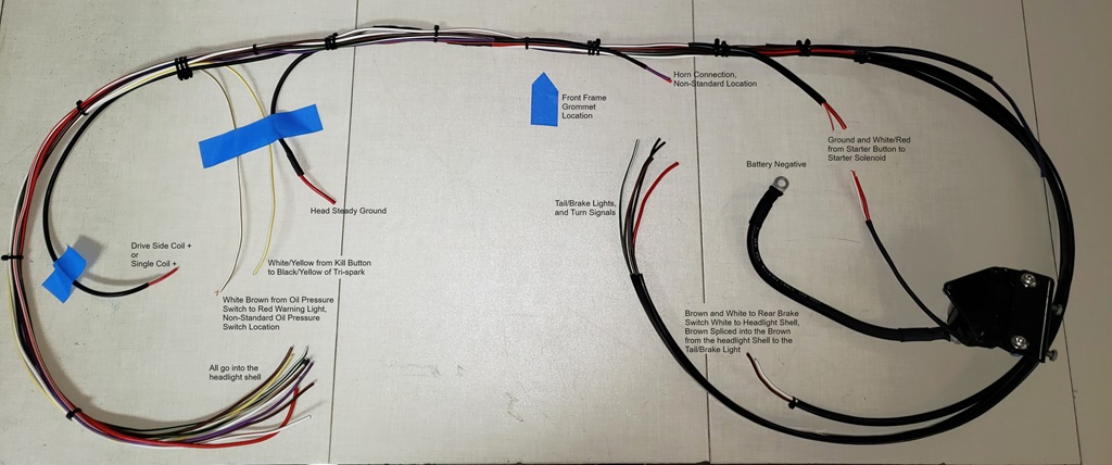
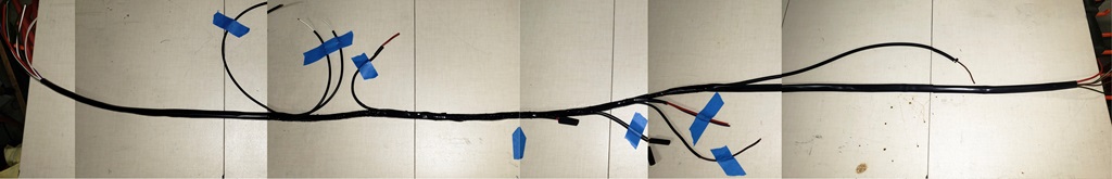
May 11, 2024 The harness is ready for wrapping. The picture is probably too small to read, but if you click on it a new tab will open with the picture full screen width.
Wherever you see three zip ties together a breakout will happen. I use two when getting ready, then with the harness on the bike I switch to three to denote the final exact location.
I'll start wrapping at the rear overlapping the sheathing for the taillight wiring and rear brake switch wiring about two inches and as I wrap forward I when I come to each breakout I will clip those zip ties, mark the next break out location with a Sharpie and remove these zip ties and any in between. That way I can straighten up the wires as I go. The goal is no twisted wires - just one of my anal-retentive things.
Besides the original wires I documented earlier, these wires were added. Note: I tried to make a picture with the harness straight and with a tape measure beside it, but it didn't work out. I'll try again once the harness is wrapped.
- White/Yellow, 18ga, 30", from the headlight shell to the breakout as shown.
- White/Brown, 18ga, 30", from the headlight shell to the breakout as shown. Note: This is non-standard for me. The owner mounted the oil pressure switch at the timing side rocker feed to the head rather than at the back of the timing cover. Normally this wire would run to that location.
- Brown/Blue, 14ga, 52" from the headlight shell to the breakout as shown. This will get the fuse holder and then either go one to the battery negative or to the starter solenoid connection to the battery negative - haven't decided.
- White, 14ga and Brown, 14ga, both 69" from the headlight shell to breakout as shown and then on to the rear brake switch.
- White/Red, 14ga, 45" and Red, 14ga. The
White/Red from the headlight shell to the breakout and the Red spliced to the main Red, both breaking out where shown.
- Purple/Black, 14ga and Red, 14ga. The
White/Red from the headlight shell to the breakout and the Red spliced to the main Red, both breaking out where shown. Note: This is non-standard for me. The owner put the horn in the normal location and ran wires out the drive side.
- The Red breakout to the head steady is 14ga and is spliced into the main Red wire.
- The Red breakout to the drive-side coil is 18ga and is spliced into the main Red wire.
- I haven't made a final decision on the Red and Black from the regulator - I will probably connect them directly to the battery and with their own fuse. They are normally connected to the main Red and the Brown/Blue behind the fuse but that seems to make more sense when the master switch is in the middle of the bike.
May 12, 2024 The harness is wrapped and on the bike. I've started terminating but there's plenty of that to go. I decided to do the regulator normally so I added a breakout for those two wires. As before, click the picture for a bigger one.
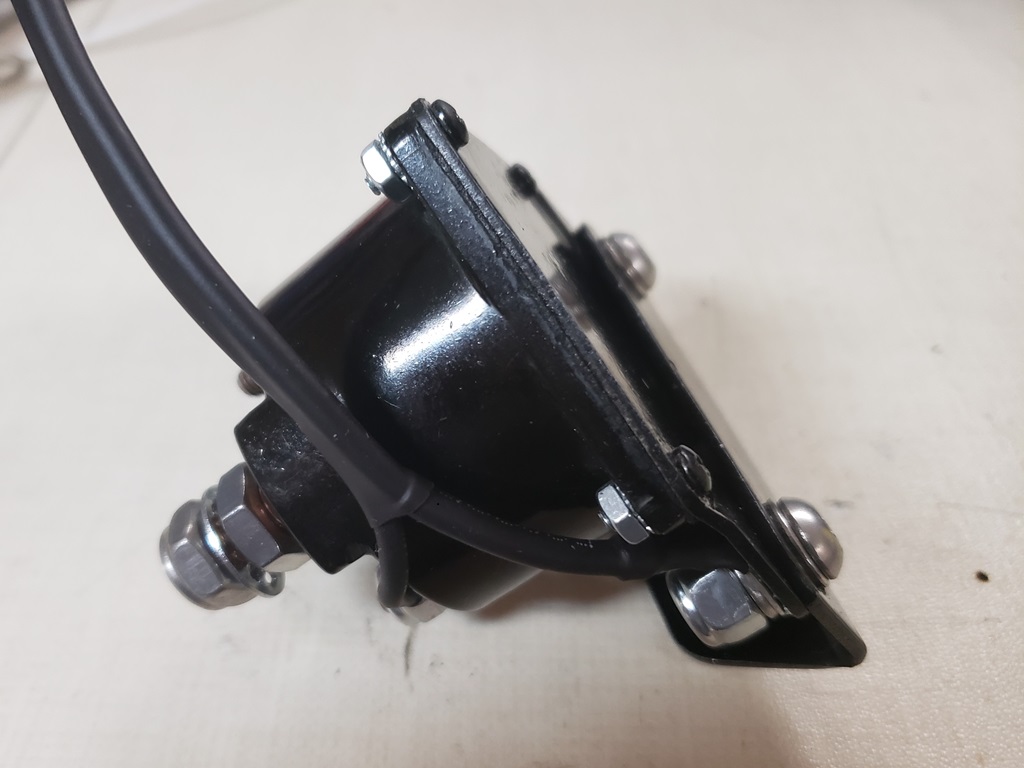
May 13, 2024 Today I tackled one of the stupid Norton engineering choices.
The Commando does not have a frame ground. The closest thing to one is that the headlight shell is grounded, therefore the fork ears are grounded and therefore the triple tree might be grounded which means that the handlebars might be grounded, and so on.
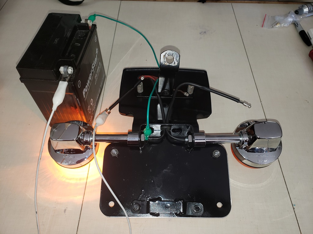
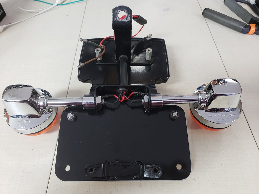
With the rectangular taillight, the tail and brake light get a ground (the red wire in the first picture), but that is grounded to the socket and may or may not make it to the turn signal mounts. It's very common to have a poor or non-existent ground for the rear turn signals. In the first picture you can see that the turn signal does not light. In the second picture, it does light because the ground is moved to the turn signal stem. In the third picture, you can see my fix.
Also, the taillight assembly was not installed correctly and was bent meaning that it pointed somewhat downward and the fairing did not sit properly. That's all been corrected. The tail light is now fully installed and end-to-end tested from the wires at the headlight shell.
May 15, 2024 Working my way forward and need to connect and test the read brake switch. Weak, tired, and don't have a lot of time today, but I did manage to move things around and move the lift I use for quick jobs into place so I can get it in the air to connect the switch - no way I can do that laying down these days - I can get down, but getting up is a real struggle!
May 16 2024 Got a steroid shot in my foot at 10am this morning. Life is about to be good for a while. Normally at about 3pm the day of the shot I enter what I call "Superman Mode". No longer need to sleep, all pain goes away, feel mentally sharper, lose inhibitions (not good), quit being careful where I walk (really bad), in general feel 15 year younger.
At 3pm I was wondering if he tricked me - no superman mode and was sleepy. Weird. Put my feet up and turned on YouTube and immediately fell asleep. At 5pm is was like Capt Picard said "Engage!" Eyes snapped open and I was in full superman mode - Yes!
OK, went out and rolled the bike onto the lift like it was nothing. Measured and terminated the rear brake switch wires and connected them. Tested and all was well. In the process I saw a wire hanging down from the bottom of the bike and wondered what the $%#* is that! Fortunately, it didn't take long to realize it was the $%#* neutral switch wire and that I had forgotten all about it in the harness - at least, that part is easy to fix, however:
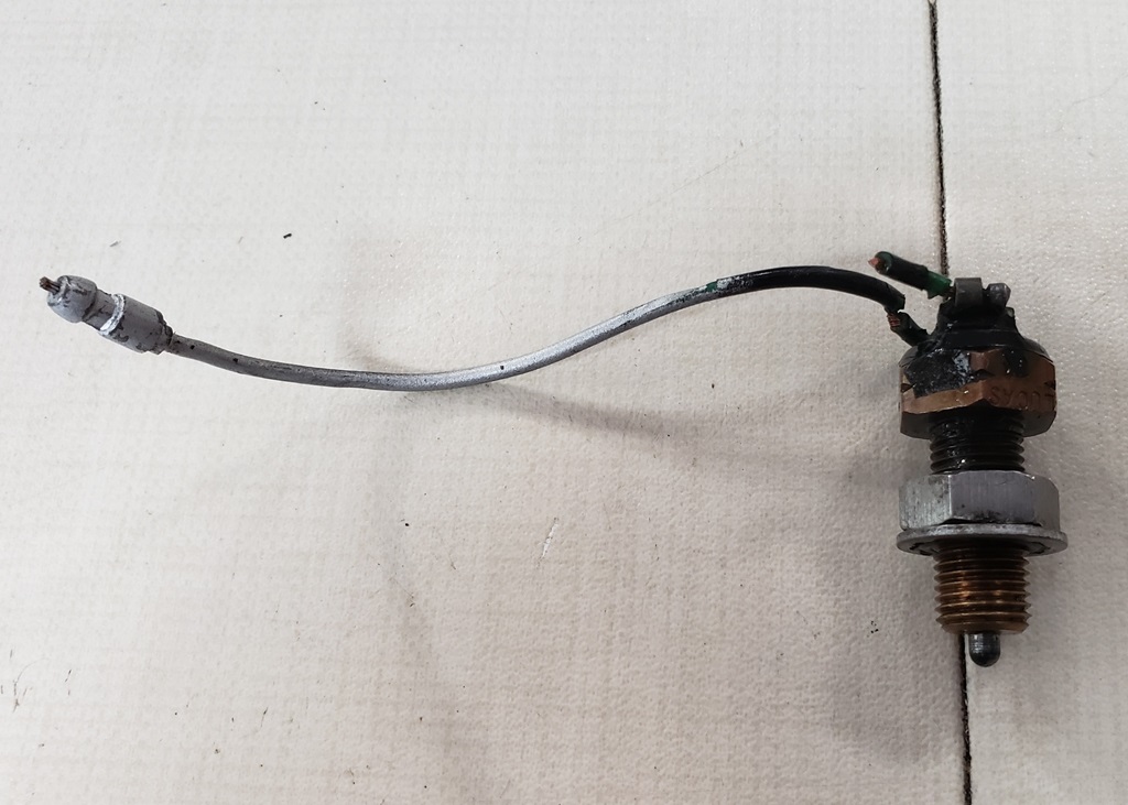
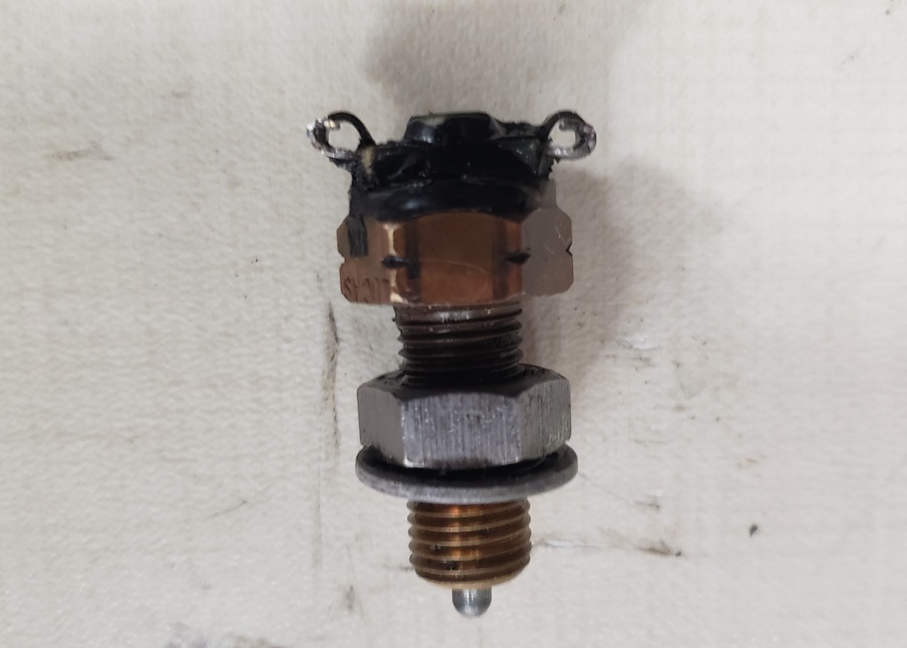
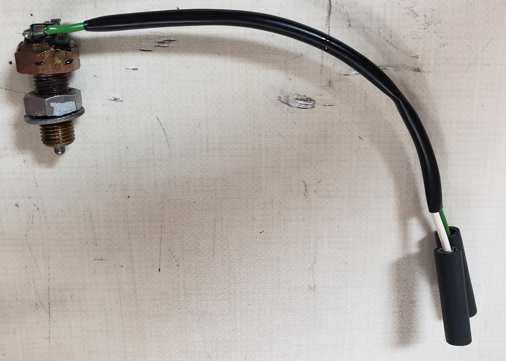
So started the MK3 neutral switch hell. I soon remembered that the neutral switch needs two wires, a white and a green but there was only one wire and it was hard as a rock. So, I removed the switch. The first picture shows its condition. The second shows after a long struggle to get the old wire out and it prepped for new wires, and the third shows it ready to re-install.
It would have been nice if hell ended there! I screwed it in to exactly the same depth as it was when I started - switch not closed. I fooled around a long time and finally
realized that although the switch was good, that it wasn't making contact with the button in the camplate. So, I put a jack under the bike and raised the rear end so I could verify that it was in neutral - nope, in the 3rd gear false neutral. So, I put it in real neutral and working on adjusting the switch. When I screwed it in far enough to reliably close the switch, I could not shift gears. When I backed it out 1/8 turn, I could again shift gears, but the switch did not close. So, the button is missing or so worn that the switch will never work. Now the gearbox must come apart to replace or install the button. At least the buttons available today have a more gentle slope and the new Lucas switches worth great with them and the new Lucas switches are not prone to leaking. I'll go back to wiring and have a discussion with the owner to see if he wants me to fix it.
Earlier today, the owner asked when I thought I would be done - most likely that jinxed me!
May 7, 2024 I swear it's easier to build bikes from scratch! It was time to take the handlebar consoles off, test them, and restore the cables. Problems!
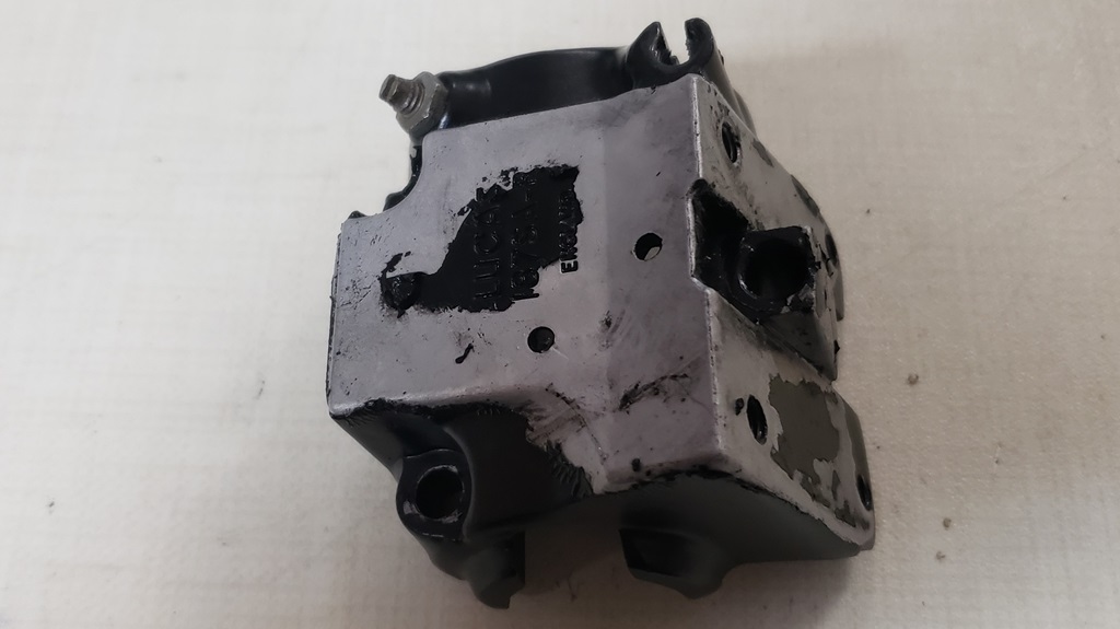
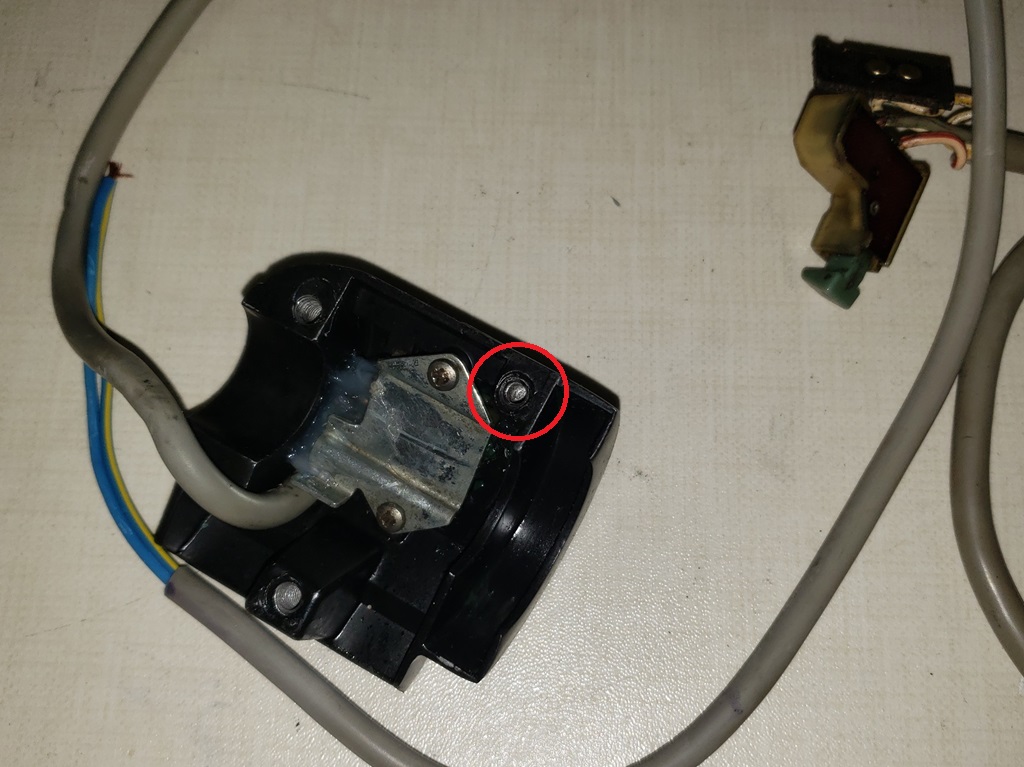
First, as I started to remove the first screw, I felt the goo on the bottom of the console. So, realizing the master cylinder was leaking, I was careful not to touch anywhere where the paint was still good. The first two pictures show the result after I got the goo and lifted paint off. Fortunately, I'm pretty sure I can make it look OK. Also, while taking it off I noticed that one screw was only in one turn. Turns out that the hole circled in red in the third picture has been Helicoiled to a smaller size. Probably 8/32 but I don't have any of those to try.
While checking things out I realized the all good screws were 10/32 - the pre-MK3 use 10/24 which is much better for soft metal.
I restore the cables all the time, but this is the first MK3 set. The covering looks similar to the pre-MK3 but it is much harder, greyer, and much harder to
make look good. They came out OK.
So, before I can put it back together and on, I need to resolved the screw hole, fix the master cylinder leak, and touch-up the parts that show.
During testing, I realized that the console is quite different from the schematic! At this moment, I don't know if it's the original that doesn't match or Grant Tillers. Since I have one in color from Grant, I've been modifying that to match what I'm doing so I'll keep going with that. One really strange thing is the start button is Write/Red as usual but the other side is normally white. The console has a white that is the hot side of the Run/Stop slider but the start button uses a Grey for the hot side. I will probably put a piece of white heat shrink on it as it will be connected to the white of the harness.
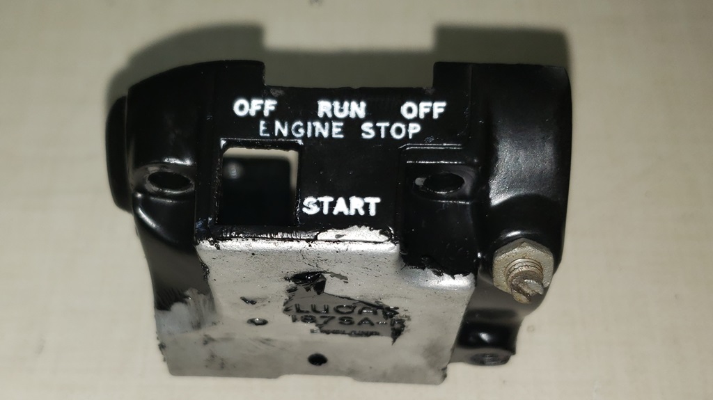
May 19 2024 It took from 11am until 6:30pm, but the handlebar consoles and restored and on the bike. I can't say they look perfect, but they do look really good. Yesterday I showed all the missing paint on the R/H side. That's all redone and most importantly the part that readily shows. See the first picture. The master cylinder is not screwed to the console because it is still leaking. The screw mystery is solved. It takes three Allen wrenches and one screwdriver to put it together. The 10/32 screw is the oddball. The hole that I thought was Heli coiled is probably not. It uses the same screws as the L/H console, and they take a 3mm Allen so they are metric. For a while, I thought they might be 2BA, but they aren't so I'm going to take one to Make Do Po and figure out the thread. The hole that is 10/32 was drilled and tapped (I think). So, to get the master cylinder off, you need a 5/32" Allen. To get the console off, you need a 3mm Allen, a 1/8" Allen, and a screwdriver.
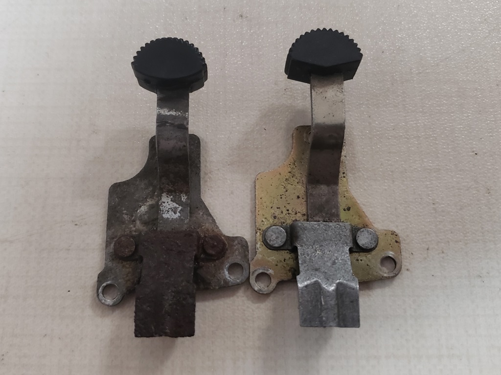
The left
side console has four identical screws all of which take a 3mm Allen. The second picture shows the worn out, rusty mess of a lever from the L/H side after me cleaning on it a long time. Fortunately, I remembered that I had one in good shape because besides the rust, it did not hold position well. The top of the L/H console also needed paint.
All the cables going into the headlight shell now have their sleeving stripped to length except the central harness. I still have to add the neutral switch wires to that. I will probably remove the central console and terminate all those wires on the bench - that will force me to think through all, so I don't fix the neutral and then remember something else.
My "Superman Mode" usually makes it to Sunday afternoon - this time it only made it to Friday afternoon so heaps of aspirin to the rescue.
May 22, 2024 I haven't updated in a couple of days but I have been working. I got proper length screws for the handlebar consols so they are properly installed now.
The neutral switch wires are now run in the harness and I'm studying creating an improvement to the neutral switch problem to stop it once and for all.
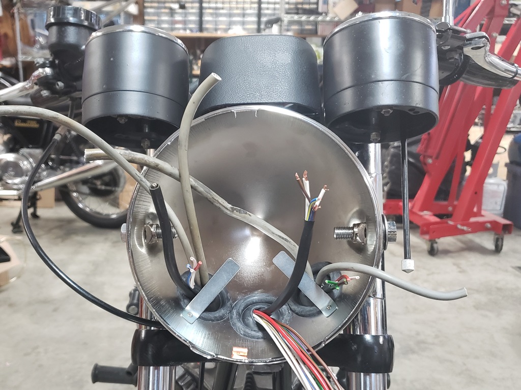
All the console wires are terminated, the headlight shell and front turn signals are on for good and almost all cables are in the headlight shell. I need to sort out the front brake switch once I've stopped the master cylinder from leaking and I need to protect the instrument lights' wires before running them.
The MK3 has more wires in the headlight shell wiring my way so routing is more important than ever - can't just plug everything in a pack it into place - I have a plan.
The headlight shell does not have the clip for the flasher. In hindsight it would have been better to put it in the pre-MK3 location, but this will work out. I thought about adding the clip with a screw in the inside and NyLock nut on the outside, but I hate to drill a hole in the
new shell - too much chance of starting rust. The connections are insulated so there no issue with it just being loose, but I think I'll stick it in place with silicone and if it ever goes bad it will be easy enough to replace.
I started to install the Tri-Spark today so I could finish the under-tank wiring but realized I'm out of Black/White and Black/Yellow wire so I placed an order this evening.
May 23, 2024 Days like today are why I never say when I'll be done! The power went out at about noon and came back on at 9:46pm. It's extremely rare to have a power outages that last more than 5 minutes here! I could not see to do the wiring and definitely could not solder so the day was wasted!
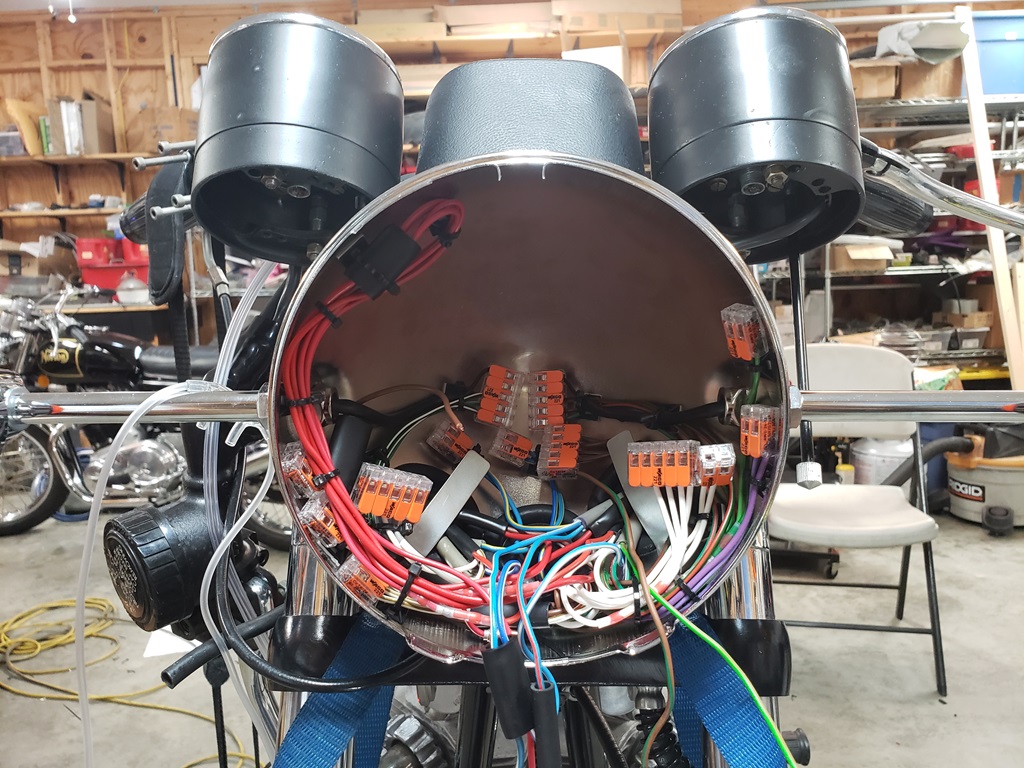
May 24, 2024 Wiring went well today. On pre-MK3, my way, the turn signals have the most wires in the headlight shell so I always to them first and test. On the MK3 there are boatloads of blue variant wires related to the headlight but I always do them last because them must be packed into the center. The turn signal wires are all neatly run hugging the inside of the shell and held down with mounts and zip ties. Basically, they take no space. And, as usual, they are tested and working fine. Next, I'll do all the other wires that simply connect together, for instance Wht/Yel to Wht/Yel and Wht/Brn to Wht/Brn and route them out of the way. I'll keep going like that until there are only Red, White, and variants of Blue wires, the Red and White go together in multi-wire connectors. Then I have to figure out the blues as all the wiring diagrams appear to be wrong. Once I have that all working I'll do the final update on the wiring diagram I'm making.
May 26, 2024 Did a little yesterday but kept falling asleep - didn't get to sleep at night and the was falling asleep all day. Today was much better. Got six good hours of sleep so I got quite a bit done. The headlight shell is finished except of the flasher - I'm out of stock. Also, the front brake switch because I can't install the leaking master cylinder. Those tow are minor to finish. I did my preliminary tests which are basically checking that I had no mis-wires causing shorts all good. The I started check each section of the lighting and the horn. All good. I still need to finish the battery area and install the TriSpark Ignition - the wire I needed arrived yesterday.
In the picture you'll see that I used very few bullets. It became clear almost immediately that the mountain of bullets would not fit. These connectors all two to five wires to enter at the same end so there are no loops required. There are seven red wires, so I did use bullets where in a couple of other places when the wires were coming from different directions like the headlight bulb socket. This came out WAY neater than usual and I'll most likely use them going forward in headlight shells. They would be really helpful in pre-ML3 because the three warning lights hang down from the top and there's nothing in the way using these.
May 27, 2024 Long day! My AC quit in the shop - not good! I remembered that my rider, which I started re-wiring long ago and have never had time to finish had a new flasher. So the that circuit is fully tested now. I already tested the front brake wiring (not the switch though) so I tried the rear - it didn't work. Of course, since I'm wiring I figured I screwed up but how - it's awfully simple.
Verified that the wiring was fine, so then I thought the switch was bad. After fooling with it for a while I realized the brake was not fully bled. Started working on that and getting nowhere. I'm not a MK3 rear brake expert so I started reading. The first thing I noticed was the workshop manual statement:
Slacken the locknut (A) and adjust as required.
Hold the shaft using nuts B and C, which are
locked together during manufacture.B & C must
not, under any circumstances, be turned in
relation to each other. Disturbing this relationship
will alter piston stroke and may render the brake
inoperative. After adjustment, retighten the locknut.
Well now, that's cool, the two nuts were not against each other! So, lots of fussing with it and bleeding, I finally got the brake light flickering. So, I assumed that the adjustment was close, and it just needed more bleeding. It's a Norton caliper - bleed until the cows come home and then some more! Once I finally got the brake working, I started zeroing in on the rod adjustment. Long story short, the brake works, the brake light works, no more air is coming out when bleeding, and there is more travel than I think there should be in the pedal. I'll ask around about that.
Started the Tri-Spark ignition wiring but by then I was way too hot and way too tired.
May 30, 2024 Worked too late yesterday to update this.The Tri-Spark ignition is installed, tested, and statically timed. Spoke with the owner - he will handle the neutral switch and master cylinder. A little more wiring to do, mostly the starter and installing the solenoid. Also finalized the deal on the Black Combat, got everything needed to send ahead boxed and off it went today.
Today was a doctor day. I may get a little done this evening - don't know yet.
Grant Tiller came through today: MK3 Commando Custom Wiring Diagram (Greg Marsh Enterprises) - Grant Tiller This is so much nicer than the one I've been modifying using Microsoft Paint.
May 31, 2024 If the good Lord's willing and the creek don't rise, this will be done tomorrow! The headlight shell is closed, the taillight is closed and everything but the starter is tested. Need to powder coat and install the bracket I made for the regulator. Then reinstall the starter motor and solenoid and test. Can't test the charging without the engine running and the owner doesn't want it started (and he didn't bring the tank). There's no reason to think the charging won't work. The master cylinder is partly J
June 1, 2024 The wiring is done except for the oil pressure switch connector. The owner didn't give me that connector. I'll have to see if I have a spare. Besides that, I need to get it off the lift and clean up. You have to get out an amazing amount of stuff and tools out to wire a bike!
June 2, 2024 All done and ready for pickup. Just have to determine how many thousands to charge for this PITA! Actually, not a PITA and took way longer than it should because I needed to figure the best way to apply my methods to a MK3. It ended up being a good job if I do say so myself and having a matching wiring diagram is a nice bonus.
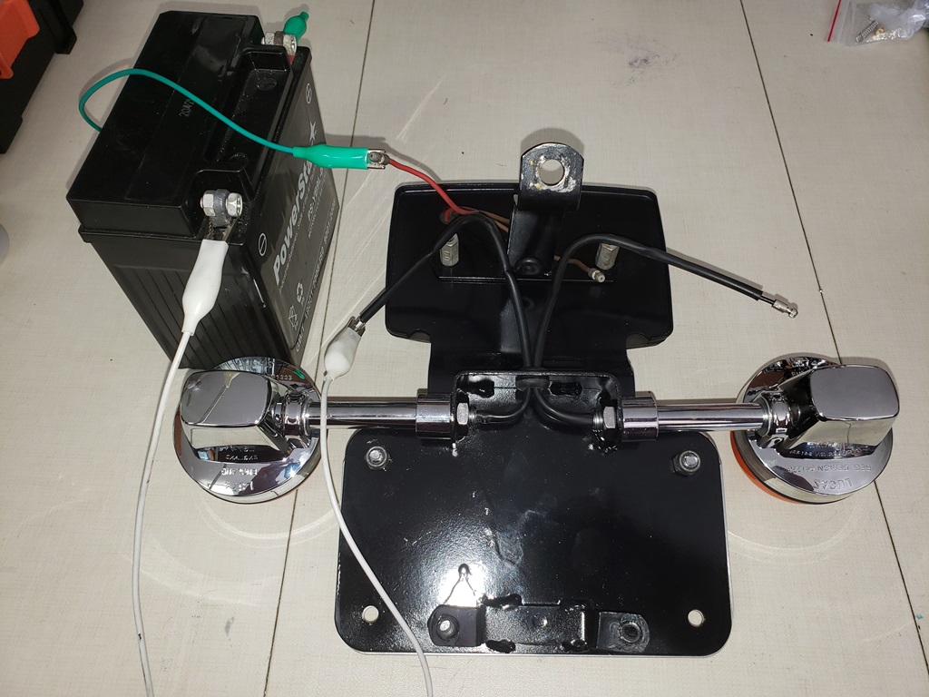
In the end, I did make the two battery connections be the two 6ga wires so there is only one connection per terminal. Rather than a small Lithium battery, the owner choose a huge AGM battery. That made wire routing in the battery area very important.
I did find a connector for the oil pressure switch and that is now installed and tested.
I ended up with no skin lost, but almost did taking it off the lift. I didn't clear out enough space and got trapped between the bike and some shelving with a crate pushing on the back of my leg - I damn'ed sure wasn't going to drop the bike and was stuck there for quite a while getting myself out of the mess - I need a keeper - you know a woman saying "be careful" every few minutes! A helper would be even better but no one wants to work anymore :-(
June 7, 2024 All done and the the bike was picked up this morning.
|